In the interest of full disclosure, I will tell you that (until recently) the entire extent of my embedded development experience was a single Linux kernel module for accessing GPIOs on a single-board computer about seven years ago. My main expertise is GUI/Application development. However, in an effort to expand my personal horizons, I’ve decided to create a simple IoT device. My goal is to write the entire system for this device from firmware to server to app and/or web front-end. What follows is an explanation of how I got my embedded Rust project off the ground.
Device Needed
I had two decisions to make: 1) which processors and chips to use and 2) which language to write the firmware in. Since this personal project is about learning new skills, I decided to use Rust instead of C. I opted to use STMicro’s Nucleo boards, since their ecosystem has shields that do all of the things I would like (WiFi, BLE, and environmental sensing), and there was also a great Rust tutorial for a similar board. However, since I’ve never really done any embedded development, I decided to start with the old standby: copying code off the internet!
Starting with the above-mentioned tutorial, I went through a couple of stages in my hello world, starting with the busy-waiting version of the blinking LED. I followed the guide relatively closely, but decided to use the latest versions of both Rust and the cortex-m-quickstart template project.
Building a Device Crate
I tried to follow the directions for building a device crate using svd2rust, which should look something like this:
$ cargo new --lib stm32f30x && cd $_

$ # Fetch the SVD from the database
$ curl -LO https://github.com/posborne/cmsis-svd/raw/python-0.4/data/STMicro/STM32F30x.svd
$ dos2unix STM32F30x.svd

$ # Patch the SVD for extra type safety
$ curl -L https://github.com/japaric/stm32f30x/raw/v0.4.0/STM32F30x.patch | patch -p1
$ cargo install svd2rust --vers 0.7.0

$ # Turn the SVD file into a device crate
$ svd2rust -i STM32F30x.svd | rustfmt > src/lib.rs
Correcting for updated versions, paths, etc., and the fact that there was no patch for the STM32F303xE SVD, my commands ended up looking more like this:
$ git clone https://github.com/posborne/cmsis-svd
$ cargo new --lib stm32f303xe

$ cargo install svd2rust
$ cd stm32f303xe
$ svd2rust -i ../cmsis-svd/data/STMicro/STM32F303xE.svd | rustfmt --force >src/lib.rs

$ cargo install cargo-edit
$ cargo add cortex-m bare-metal vcell
$ cargo build --target thumbv7em-none-eabihf
As of 8 April 2018, you can use cargo to build the library. If you are using an older nightly, you’ll need to use xargo.
So far, so good. However, as I was getting my program that used this crate to work, I ran into other issues, such as this bit from the cortex-m-rtfm documentation:
If targeting a Cortex-M7 device with revision r0p1 then you MUST enable the cm7-r0p1 Cargo feature of this crate or the Resource.claim and Resource.claim_mut methods WILL misbehave.
and, after running into a linker error about missing interrupt handlers, I found this in the svd2rust documentation:
If the “rt” Cargo feature of the svd2rust generated crate is enabled the crate will populate the part of the vector table that contains the interrupt vectors and provide an interrupt! macro that can be used to register interrupt handlers.
The final dependencies in Cargo.toml ended up as:
[dependencies]
vcell = "0.1.0"
bare-metal = "0.1.1"
[dependencies.cortex-m]
version = “0.4.3” features = [“cm7-r0p1”]
[dependencies.cortex-m-rt]
optional = true version = “0.3.0”
[features]
rt = [“cortex-m-rt”]
I also ended up adding my own enumeratedValues to the SVD before finalizing the crate (so there is, in fact, a patch to the SVD now), which you can find on crates.io or github.
Busy Wait Blinky
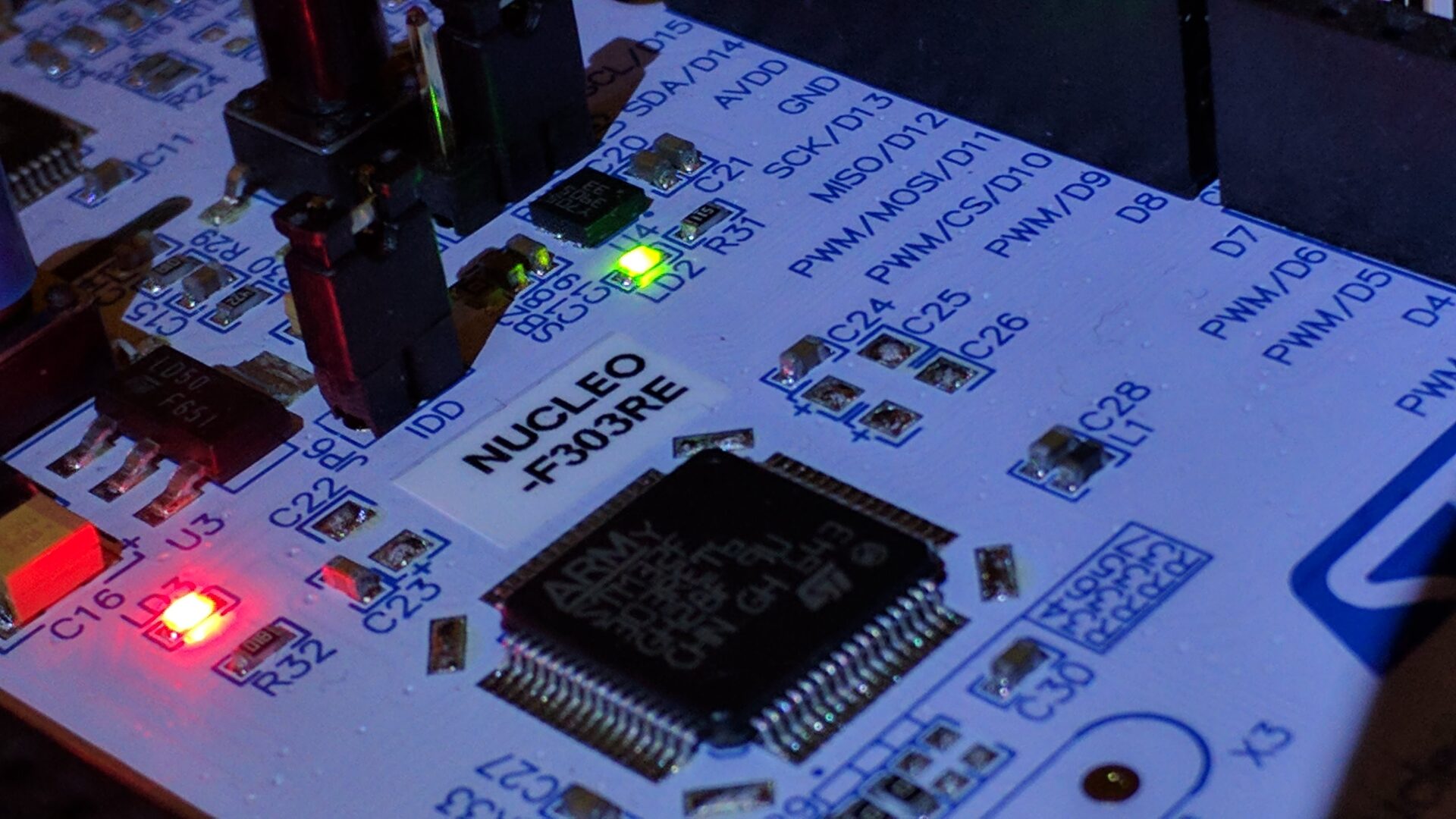
Technically, my first attempt was the literal “Hello World” program that prints to the debugger, but you can refer to Jorge Aparicio’s post for that; it worked without any changes. The next bit was copying the LED blinking program that used a busy wait. This program almost worked without changes, but the user LED on the Nucleo is connected to a different pin than it is on the Discovery. To find out which one, you need the user manual for the Nucleo F303RE, which says
User LD2: the green LED is a user LED connected to Arduino signal D13 corresponding to STM32 I/O PA5 (pin 21) or PB13 (pin 34) depending on the STM32 target. Refer to Table 11 to Table 23
Table 14 has the description of the Arduino connectors for the F303RE, which indicates that Arduino signal D13 corresponds to PA5, which is used for SPI1_SCK, with no mention of LD2 or an LED. I ended up trying both PB13 and PA5, and PA5 was the one I wanted.
In my initial bring-up, I had not yet added enumerated values to my SVD, so I also had to replace some of the calls that used those wrappers with direct, generic, calls that manipulated the bits, such as
// In the original:
tim7.cr1.write(|w| w.opm().continuous());

// ...became
tim7.cr1.write(|w| w.opm().clear_bit());
The correspondence between enumerated value and bit value can be found by deciphering the user manual for the processor, which says (on page 678, describing TIM6/TIM7’s CR1 register)
Bit 3 OPM: One-pulse mode
0: Counter is not stopped at update event
1: Counter stops counting at the next update event (clearing the CEN bit).
Interrupting Blinky
As japaric says at the end of his initial post, this initial blinky program
is blocking code that forces the processor to uselessly busy wait for a whole second when it could have been doing something more useful.
His next post introduces cortex-m-rtfm, which uses interrupts to coordinate concurrent tasks. Since I am trying to use the latest and greatest, I ended up having all sorts of issues, as the code from that post wouldn’t work. Eventually I discovered that I was using cortex-m-rtfm v3, which has a much simpler (though very different) API from v1 described in that post. There is a great introduction to v3 by japaric as well, though the one task example that is packaged with the source is exactly an interrupt-based program to blink an LED. Update some pins, and presto-chango we have a working, efficient, blinking LED!
The factory firmware for the Nucleo-F303RE has a blinking LED, but also lets you cycle between 3 frequencies by pressing the user (blue) push button on the board. This, I think, would be a good exercise to ensure I can go beyond the tutorial blogs. I’m new to embedded development, so I wrote out what I knew I needed:
- Which pin is the user button on?
- Which interrupt gets called when that button is pressed?
After consulting the manual for the Nucleo, I found that the button is connected to PC13 (i.e., GPIO-C, pin 13), which should trigger external interrupt 13. But wait, there is no external interrupt 13, only an external interrupt 15–10, though that seems a likely candidate.
So I update my init function to enable GPIOC, and set up my RTFM task for EXTI15_10 to cycle my LED frequency… and my LED is still blinking at 1 Hz.
After a bit more digging around in the user manual, I find that external interrupt 13 (EXTI13) is not automatically connected to PC13, but can actually be used by pin 13 from any GPIO (though only 1 at a time). To configure EXTI13 to be triggered by PC13, I have to configure EXTI13 using SYSCFG_EXTICR4 (system configuration controller external interrupt configuration register 4), bits 7–4 to be 010, which svd2rust makes relatively straightforward:
p.device.SYSCFG.exticr4.modify(|_, w| unsafe {
    w.exti13().bits(0b010)
});
With appropriate use of enumerated values in the SVD, we could eliminate the unsafe block, so it would read
p.device.SYSCFG.exticr4.modify(|_, w| w.exti13().pc13());
While this doesn’t exactly read like eloquent prose, it does closely match the language in the user manual, which lets the reader look up the documentation for this magic incantation.
The latest version is available on github.
Onward!
If you followed japaric’s “Rust your ARM microcontroller!” post, but found that it doesn’t quite accord with the state of the art, hopefully this post has pointed you in the right direction. I’m well aware this is not a step-by-step guide, but is more of a landmark-oriented description of how I got my embedded Rust project off the ground.
I’ve barely scratched the surface of both Rust and embedded programming, but the most important lesson I’ve learned so far is: documentation is king. For all things embedded, check the appropriate user manual (mostly for the chip, but some information is particular to the finished board). For Rust, the source code is the ultimate arbiter of truth. Cargo downloads all dependencies and places them in ~/.cargo/registry/src. Your Cargo.lock file has the exact versions you’re compiling against, so you can check the appropriate crate’s source.
You can follow my progress by following 219 Design on LinkedIn, Facebook, or Twitter where new updates will be posted. Also, check out my other posts at: https://medium.com/@pdanielgallagher