At 219 Design we regularly architect and implement smart products from the ground up. To date, we’ve completed more than 1000 projects with more than 100 clients from startups to large corporations for almost 20 years.
We imparted some of that experience recently at the Sensors Converge 2021 conference. Dave Bim-Merle and I gave a presentation titled “Architecting Firmware Applications with Multiple Sensors.” One of our conclusions was that FreeRTOS can be a powerful solution for many applications, in particular ones that involve periodic tasking like sampling multiple sensors.
We designed and implemented a public demo project on GitHub using a dev kit to provide an easy way to get up and running fast with FreeRTOS. Try it out!
Demo Project Quickstart
For those of you that want to just jump to the good stuff:
Step 1: Download the project from GitHub
Step 2: Follow the README to get running
Step 3: Profit
For those of you that want more background, read on for the details.
Our Approach for Creating the Demo
Step 1: Capture Requirements
One of our guiding philosophies with product development is that up-front design reduces the overall schedule. We applied the same principle to the demo project. Usually we start by asking ourselves and/or the client the following questions:
- Functional Requirements: What does this need to do?
- Timing: Are there “hard” timing requirements?
- Priorities: Are some things more important than others?
- Preemption: Do any tasks need to “cut in line”?
- Testing: How will you ensure it is doing the right thing?
Once we have a definition of what needs to be built, we move on to how. An important early decision is the execution model of the application, or how it implements functionality over time. There is a spectrum of execution models, from round robin up to a full operating system like Ubuntu or Windows.
Step 2: Choose Execution Model
We won’t go into an exhaustive list of trade offs here beyond some high-level observations. Usually it is best to keep it simple. Not all applications need to use embedded Linux or an RTOS. We chose FreeRTOS because we wanted to leverage its ability to multitask sampling multiple sensors in a periodic manner.
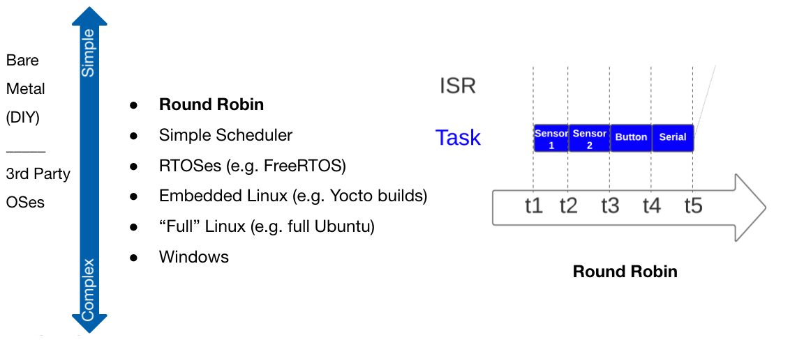
Round Robin
For a simple application, a round robin approach could work. The main drawback is that if the time to do a task changes, there is a direct effect on following tasks:
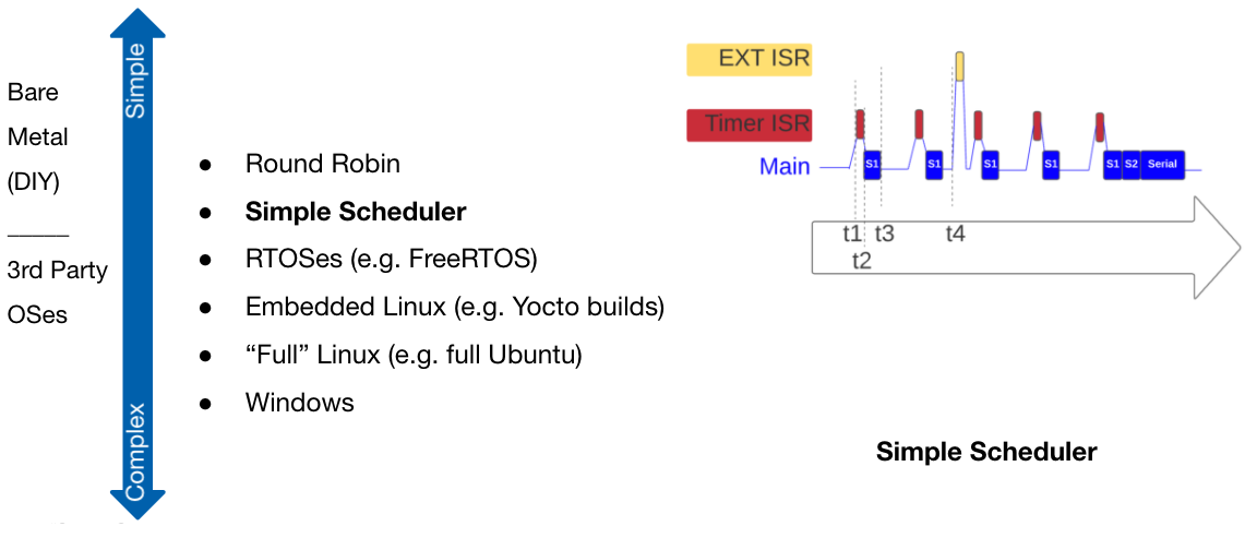
Simple Scheduler
The next level of complexity, a simple scheduler, brings time into the execution. Normally these use some kind of a timing tick or timebase and a period to perform a task. This helps decouple the timing of the separate tasks, but there can still be latency on following tasks if a task takes too long to complete.
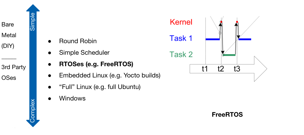
RTOSes
An RTOS helps with the scheduler’s limitation by using task preemption. If a task must run, then it can interrupt (preempt) a lower priority task. Usually an RTOS will be based on an internal scheduler which can be leveraged by the application. Why reinvent the wheel?
In the right circumstances, using the scheduler built into the RTOS can make parallel task needs (multitasking) much easier. Our demo project illustrates this benefit by sampling multiple sensors periodically. The periods of the tasks are also decoupled from each other. One drawback though is that execution can be less deterministic making some bugs harder to resolve.
Aside: There are many RTOSes out there. The benefits of FreeRTOS include being integrated with other open source software (STCube, AWS IoT, etc), having a large community, using an open license (not commercial), being open source, and having good documentation. There are a lot of open source options out there (see an example list here). Applications where safety certifications are needed will likely need a commercially licensed, closed source RTOS.
Step 3: Design the Architecture
Once it is chosen how the application is going to execute, the architecture of the application must then be determined. Ideally, it is peer reviewed to root out any obvious issues. It is orders of magnitude easier to change a design at this stage than once it is implemented. Usually this involves determining the layers of the code (typically low-level drivers/HAL, middleware, and application). One easy way to do this is to create a diagram like the following from a real project we did:
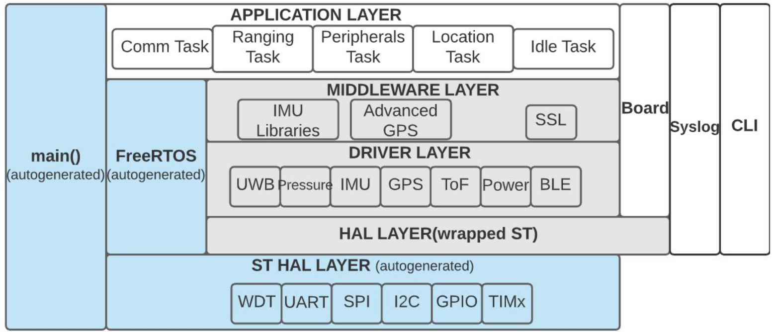
In the above graphic, modules can only call into other modules laterally or below to an adjacent module. They cannot call above (e.g. pressure into comm task) or skip layers (e.g. location task into SPI). Color coding the modules, as done above, helps with organization to mark those that are auto generated (blue), and those that will be unit tested (grey), as well as any 3rd party libraries.
Step 4: Partition the Necessary Functionality
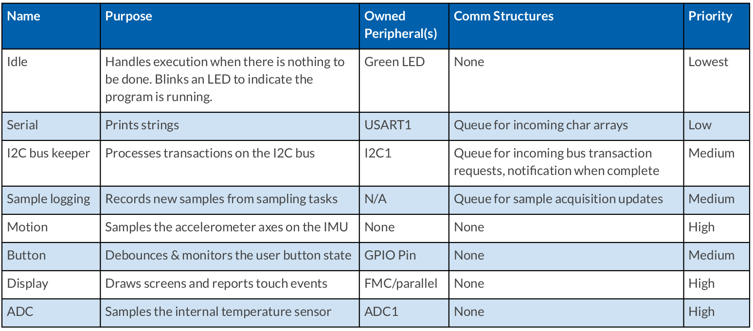
The next step that is often helpful is a table of tasks or functionality. Essentially this lists what needs to be done, who does it, and ownership of resources. This is more beneficial for an RTOS or an application that uses a scheduler, but the concept could be applied to other execution models. The table from the demo project is copied here.
Step 5: Implementation
Now that the high-level design work has been done, the plan of action should be mostly clear. The first order of business is to set up source control and the development environment (IDE, compiler toolchain, other software tools, etc).
In terms of features, it’s usually best to start with the more basic ones and gradually move up to the complicated. Implement a feature, test, and move on. Here, we got the idle task working first to know that the development environment, FreeRTOS, clocks, etc. were configured correctly. We already knew the dev kit likely wasn’t a dud since it ran ST’s preflashed example. Once we were blinking an LED we then moved on to the serial task, I2C, and upwards.
During this step, it is a good idea to go back and update the documentation to reflect the current state of the design as it changes. Details unforeseen during the design stage come out once the firmware begins to interact with hardware and assumptions are tested.
The Result: Sensors Converge Demo
For the Sensors Converge 2021 conference, we wanted to provide attendees with a project that would jumpstart RTOS usage with a simple example. Our demo uses a relatively new dev kit from ST that is available for purchase from multiple distributors or directly from ST. The dev kit itself has much room for expansion in terms of the available sensors to sample, a touchscreen, and more. There are more details in the README on GitHub.
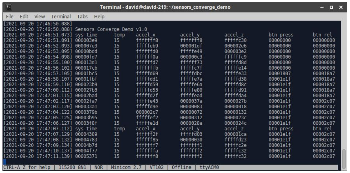
The main goal of the demo was to allow the user to unpackage a fresh dev kit, flash the provided binary, and see it working without any hardware configuration or nontrivial setup. All one needs to do is download the release binary, flash it, and open a serial terminal. The easiest output to the user was printing values over the serial port as shown, and you can get there in just a few minutes.
You can also download the source code and quickly modify it to change the period of sensor sampling, add additional sensors or outputs, or use it as an initial architecture to kickstart a different project. The demo project was intended to be reasonably generic in order to facilitate understanding and reuse.
We’re Here to Help
Thanks for taking the time to read our post. Don’t forget to head over to our GitHub page and check out our demo project. We’d be happy to answer any questions, comments, or address any issues.
We hope that the content presented here as well as the demo project inform your current and future embedded systems projects, and help you get up and running fast. 219 is always on the lookout for the next engineering challenge, be it firmware, electronics, software, or mechanical. We’d be happy to see how we can add value to your project. You can reach us by clicking “contact us” below or at getstarted@219design.com.